Next up, it was time to build something that actually made some noise!
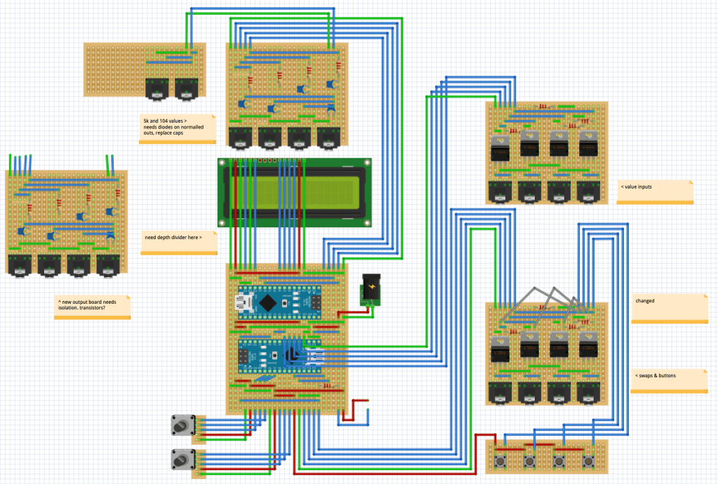
My goal was to create four discrete outputs, each of which would be fed into a VCA controlled by the four lanes from my sequencer. Each output should contain a different note, and these should make up a chord. This device would then need to be controllable via an external CV source. I had a think, and decided that my chords would be defined by four parameters:
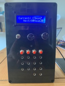
- Root note (A through G, always using sharps rather than flats)
- Octave of root note (0-5)
- Chord type (major, minor, 7th, minor 7th, dominant 7th, diminished, 6th, minor 6th, augmented, augmented 7th, suspended 2nd, suspended 4th, powerchord, octaves and stacked major 3rds)
- Inversion (A-C as normal inversions, and 1-3 where the root note is pushed down 1,2 or 3 octaves)
I would then allow either the currently output or the ‘next chord’ to be modified by either rotary encoder or CV input, and then have a set of buttons and trigger inputs which switch between the two.
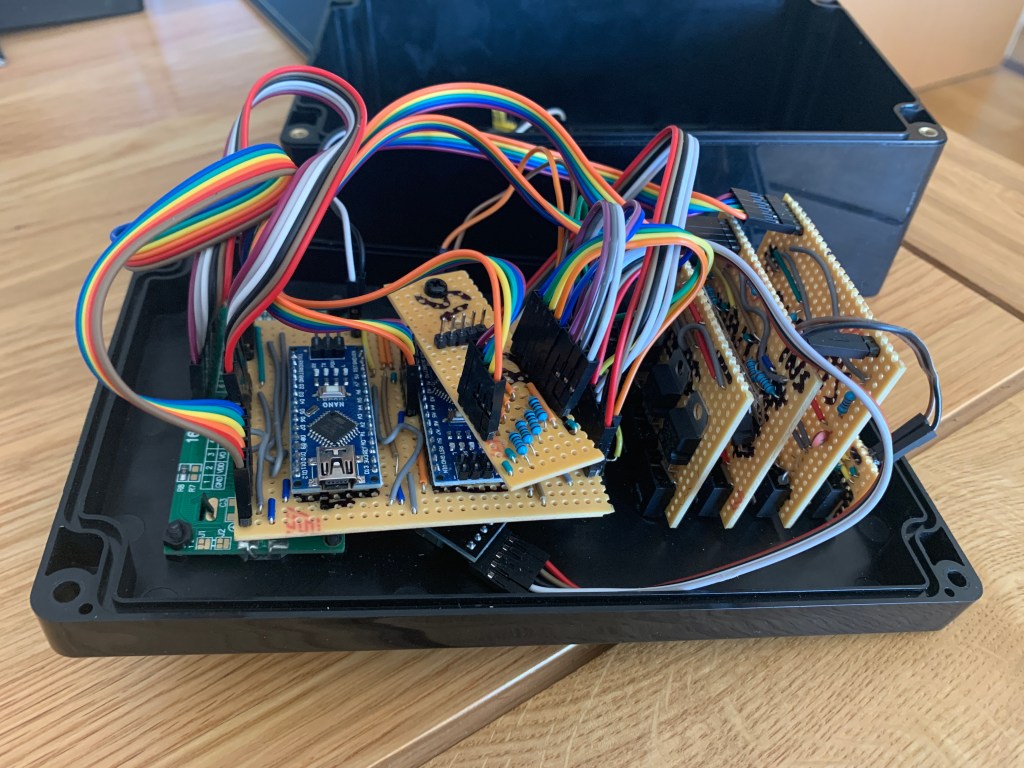
As analogue oscillator circuitry was still beyond my understanding, I decided to use Arduino to digitally create square waves at controllable frequencies as my sound sources. I found a library which allows each NANO to output two accurate square waves, but unfortunately I could not generate all four from the same board, meaning the two boards are used in this circuit – one managing all of the inputs, deciding what notes should be played and outputting the first two pitches, and the second just listening to commands from the first and outputting the other two signals. This meant learning how to get the two boards to communicate, for which I used the Wire.h library.