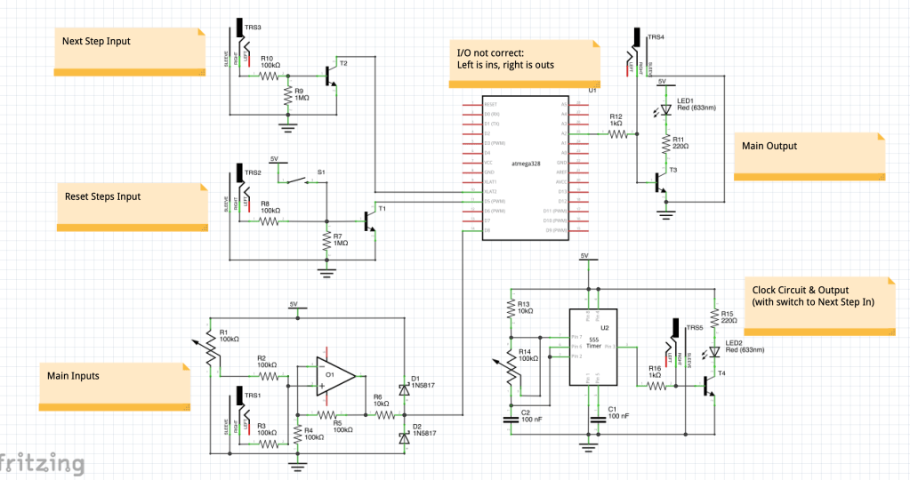
Today was another busy day – I completed the majority of the code for the module, and also worked on plans for some of the analogue circuitry required!
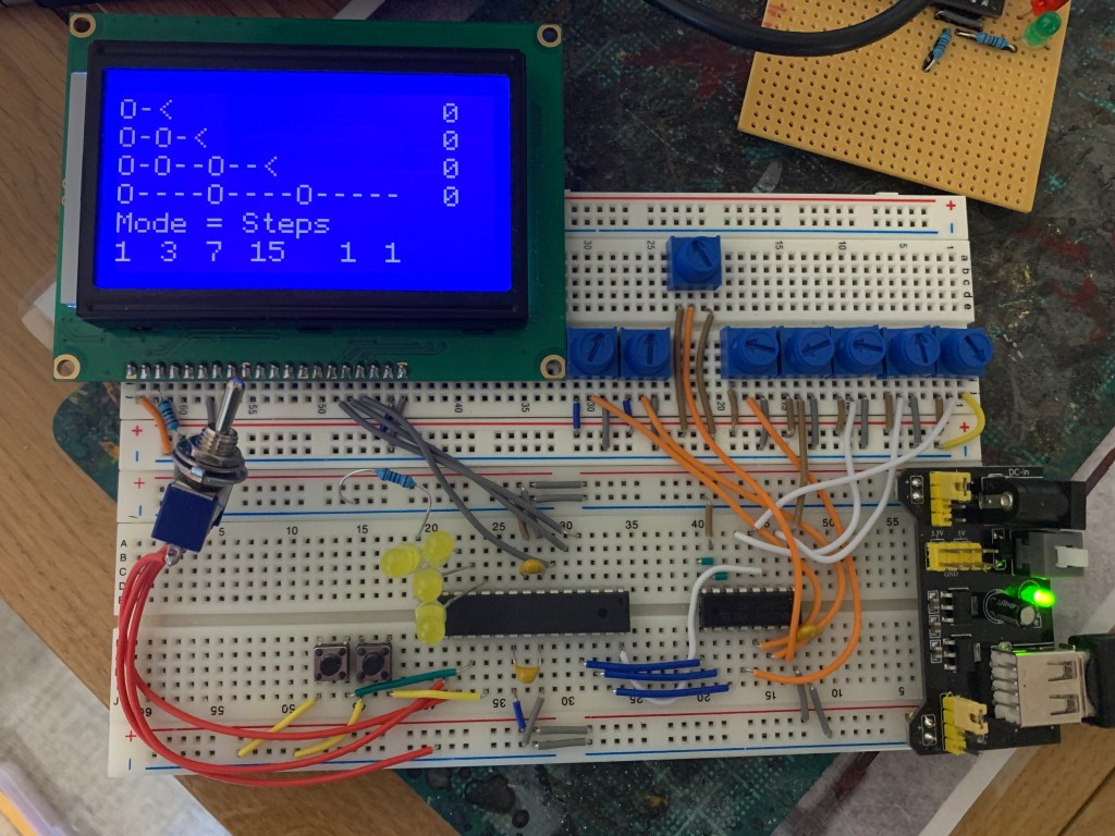
The ‘Next Step’ and ‘Reset Steps’ input buttons now function, and the module can step through sequences and blink the yellow LEDs at the appropriate times. Once hooked up to my analogue clock circuit this will mean I have a working sequencer!
While the current display is only temporary (I think it will be too big to use on the final module), I did a bit of work on the displayed information to help with debugging. The sequences now display as “O” and “-” characters to make things easier to read, and blank out any unused steps in sequences below 16 steps. The zeros at the right in the picture show the offset values for each lane, and the first four numbers underneath show the next step for each lane. The last two ‘ones’ are to do with the next step button state as I had a few issues getting this to work.
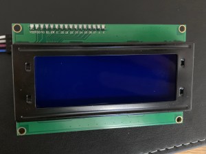
An alternative screen turned up in the post today – this one is a 20×4 character display – enough room to show all four lanes with a few spaces for some extra info. Unfortunately, it turns out it is nearly as big as the 128×64 pixel display I am using in the prototype! I will need to do some measurements and figure out displays further down the line…
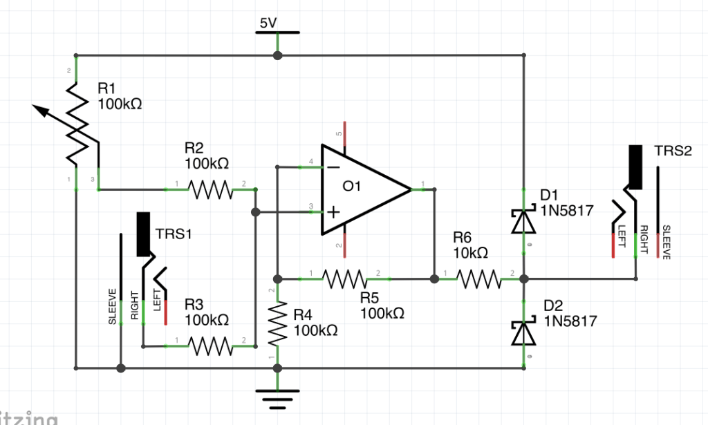
I also did some more work on the analogue schematic from yesterday. I had posted this on Reddit, asking for suggestions (or to see if I’d done anything stupid!), and got some good advice and a great link to the schematics to Mutable Instrument’s Grids, which is fundamentally similar to my module. I decided to stick with my input/output plans rather than copying MI’s as theirs require ‘rail-to-rail’ op amps which are far more expensive than the ones I was hoping to use. I did however manage to use their advice to minimise my circuit down to a single op-amp. I built this and tested it, although I am still waiting on my Schottky diodes so cannot yet confirm whether the voltage regulation is effective.
I also did some first drafts of the other input and output circuits and my 555 clock generator, and ordered the transistors needed to build and test them.