Today I tested a couple of the circuits from my previous post with the diodes and transistors that had arrived over the weekend. I made a couple of small tweaks but nothing groundbreaking.
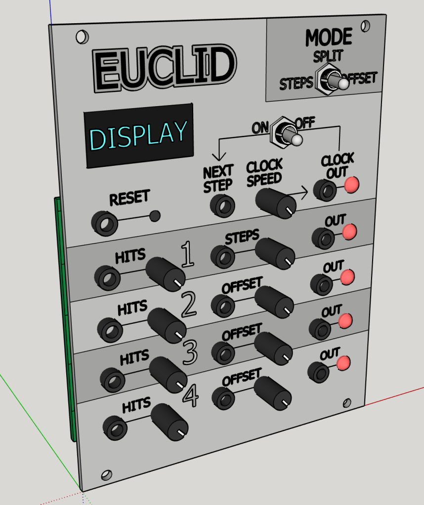
My big job for the day was creating a scale model of the faceplate in CAD, to allow me to figure out how big the module needs to be and therefore what size display I can realistically fit onto it. After placing the required controls and jacks with enough space to comfortably turn the knobs (hopefully!), I ended up needing a 20HP wide module. This does not leave enough height for any of the display types I have been prototyping with, but does leave enough for a 1.3″ LCD, similar to the one I used on the car model described earlier in this blog. Annoyingly, most displays seem to have a footprint much larger than their useful screen area. The design layout and wording is just a first draft, but I am pretty happy and would imagine the finished module will look somewhat similar to this.
I also did some research into PCB printing and it looks like I will need to either spend a lot of money to get these produced in the UK (£100+!) or go with a Chinese producer that could take over a month to arrive. As I will need two boards – one for the I/O components and one for the rest of the circuitry, I will likely need to go with the Chinese option.

