Yesterday I popped in the University to get my test faceplates laser cut, and while I was there I picked up the UH Modular System to do some testing with.
Firstly, my module does indeed fit into the case and the screw holes are in the right places! As mentioned in my previous post, the faceplate is thicker than planned, so I couldn’t actually screw it in place, but it definitely fits!
I had a play around and tested out all of the parameters, both by connecting Axiom with the other modules and checking that I got the expected results, and also by comparing my outputs to similar gate outputs (particularly on the Moog Mother 32) using an oscilloscope.
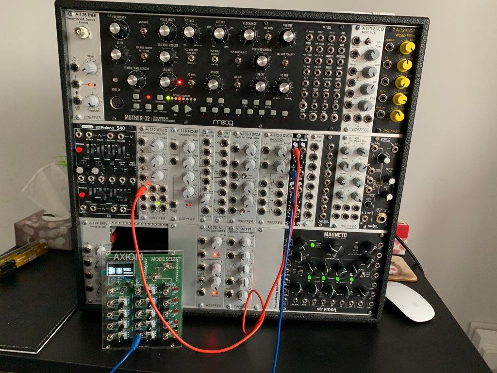
The results were generally very good. Everything worked as expected! My outputs are slightly low in voltage, at 4.63V rather than the 5.02V the Moog puts out, but every module was successfully triggered but this, so I am not too concerned. The CV inputs work, but give a more useful range of control when the usual 10V swing of a CV signal is halved by an attenuator module, so I will see if I can modify my circuit to do this internally (a simple resistor ladder should achieve this if there is physically space to mod the board).

