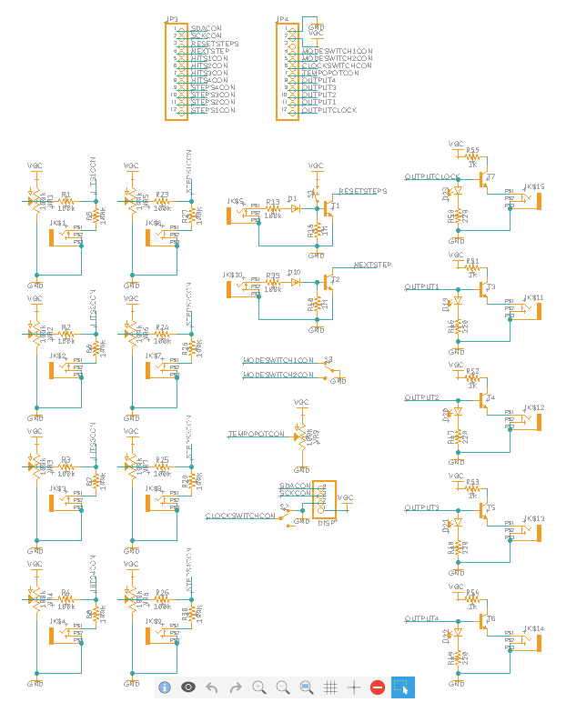
The next step was to design my circuit board layouts using the schematic I had designed, but unfortunately I quickly came to a frustrating realisation – Fusion 360 will not let you create multiple boards from one schematic!
This meant that I had to split my schematic in two – one half for the I/O board with all of the jacks and pots, and a second for the logic board with all of the ICs, voltage regulation and power input. Both schematics also needed a pair of header pins to connect the two boards.
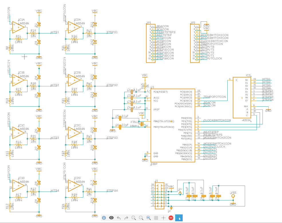
The ‘logic board’ also gained some extra decoupling capacitors (these are attached to the power pins on the schematic but will realistically be as close to each IC as possible), and I also added the 16MHz crystal to the ATMEGA328p. I do not necessarily need to actually solder this to the circuit board, but it will be much easier to do this if the board is designed for it!

