Last week I built another prototype of the module on stripboard. As designing and building stripboard takes ages I didn’t do the whole thing, but just a single lane of the sequencer and all other ancillary circuits. The input circuits and voltage limiting worked perfectly, but the output circuits were outputting a rather wimpy 4.2V (I am aiming for 5V). Also, something went wrong with the 555 clock circuit. I spent a good few hours trying to figure this out but could not crack it. During the testing process I realised that the duty cycle of the clock would present an issue if used to trigger other modules at high speed (the duty cycle for an astable 555 circuit must be a minimum of 50%).
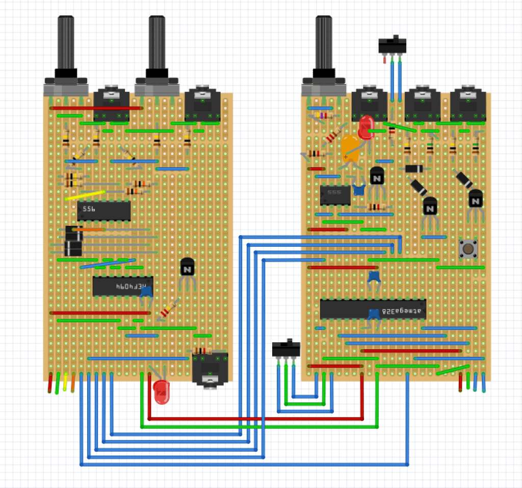
To combat these problems, I made a tweak to the output circuit (the output jack is now driven by the transistor and the output from the IC pin is connected to the LED – these used to be the other way around). I also decided to completely scrap the 555 circuit and use the microprocessor to generate timing instead. This will look identical to the user, with the corresponding speed pot now just connected to an ADC on the IC instead of to an analogue circuit. It also gives me the advantage that I can display the tempo on the display (if there is space), and can set my high/low values and the response curve more easily. It also eliminates the duty cycle issue, and reduces the size of my circuit.
Unfortunately, due to my newly realised need to rush things, the updates to the code to add in the timer are not written yet, and in fact nothing has been tested beyond this point – everything has been based entirely off theory (and my previous tests). Hopefully the updated schematic and board designs in my next few posts do not contain any mistakes, as If they do I will not find out until much further down the line!

